What are L Finned Tubes, LL Type Finned Tubes, KL Fin Tubes
L Type Finned Tubes (L Foot Fin Tubes)
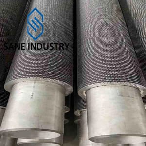
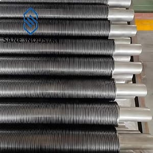
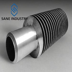
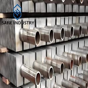
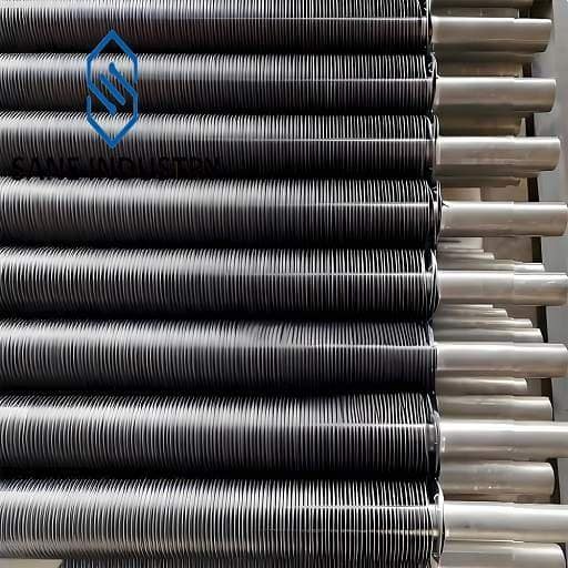
- Structure of L Type Finned Tubes: A continuous strip of metal (e.g., aluminum, copper) is mechanically wrapped around a base tube in a helical pattern. The fin’s “L” shape (like a folded tab) provides a secure grip on the tube.
- Key Features of L Type Finned Tubes:
- Moderate surface area enhancement.
- Good mechanical strength and durability.
- Cost-effective for standard applications.
- Applications of L Type Finned Tubes:
- Boilers, air coolers, and HVAC systems.
- Medium-temperature environments (e.g., oil refineries).
LL Type Finned Tubes (LL Fin Tubes)
- Structure of LL Type Finned Tubes: Similar to L-type but uses double-layered fins (two overlapping “L” strips) to create a denser, more tightly packed fin arrangement.
- Key Features of LL Type Finned Tubes:
- Higher heat transfer efficiency due to increased fin density.
- Reduced risk of fin loosening under thermal cycling.
- Applications of LL Type Finned Tubes:
- Condensers and evaporators.
- High-moisture or corrosive environments (e.g., chemical processing).
KL Fin Tubes (Knurled L fin tubes)
- Structure of KL Fin Tubes : The base tube surface is knurled (textured) before the L-shaped fin is wrapped around it. The knurling creates grooves that lock the fin in place.
- Key Features of KL Fin Tubes:
- Superior fin-to-tube bonding strength.
- Resistant to vibration and thermal expansion/contraction.
- Applications of KL Fin Tubes:
- High-vibration environments (e.g., power plants, compressors).
- Extreme temperature fluctuations (e.g., industrial furnaces).
Structural and Design Differences of L Type Finned Tubes, LL Type Finned Tubes and KL Fin Tubes
Type Fin Design Bonding Strength Best For L Type Finned Tube Single helical strip Moderate Standard heat exchangers LL Type Finned Tube Double-layered fins High High-efficiency, corrosive environments KL Fin Tubes Knurled base Very High High-vibration, extreme temperatures - Performance Characteristics Comparison of L Type Finned Tubes, LL Type Finned Tubes and KL Fin Tubes
- Heat Transfer Efficiency:
- L Type Finned Tube: Less efficient in terms of raw heat transfer, excel in condensing applications where their low-profile fins optimize condensate distribution.
- LL Type Finned Tube: Generally offer the highest heat transfer efficiency due to their extensive surface area and turbulent flow characteristics.
- KL Fin Tube: Follow closely the LL Fin Tubes, particularly in applications where the knurled base enhances heat transfer.
- Pressure Drop:
- L Type Finned Tube: Typically have the lowest pressure drop among the three types, making them suitable for applications where flow resistance must be minimized.
- LL Type Finned Tube: May be more prone to fouling due to their complex flow paths and increased surface area.
- KL Fin Tube: Follow closely the LL Fin Tubes, exhibit moderate pressure drop.
- Fouling Resistance:
- L Type Finned Tube: Generally offer the best fouling resistance due to their relatively smooth surfaces.
- LL Type Finned Tube: Generally offer the highest heat transfer efficiency due to their extensive surface area and turbulent flow characteristics.
- KL Fin Tube: Have moderate fouling resistance.
- Mechanical Strength:
- L Type Finned Tube: May be more susceptible to fin detachment under extreme conditions.
- LL Type Finned Tube: Offer good mechanical strength from their spiral wound construction.
- KL Fin Tube: Typically provide the highest mechanical strength due to the knurled base design, which enhances fin adhesion.
- Heat Transfer Efficiency:
The Manufacturing Process of L Type Finned Tubes, LL Type Finned Tubes, KL Fin Tubes
Material Preparation
- Base Tube: Typically made of carbon steel (ASTM A179/A192), stainless steel (AISI 304/316), or copper alloys (C12200). Wall thickness ranges from 1.5–4.0 mm, depending on pressure and temperature requirements.
- Fin Material: Aluminum fins (AA1100/AA1060), copper fins, or corrosion-resistant alloy fins (e.g., titanium). Thickness: 0.4–1.2 mm, pre-cut into strips for L-shaped bending.
L-Fin Formation
- Cold Rolling & Bending: Pre-cut metal strips are fed into a forming machine with L-shaped rollers. The strip is bent at 90° to create the “L” profile.
- Edge Trimming: Laser cutting or mechanical shearing removes excess material to achieve clean fin edges.
Fin Attachment to Base Tube
- Hydraulic Expansion:L-fins are positioned around the base tube. A hydraulic mandrel expands the tube radially (pressure: 50–120 MPa), forcing the tube wall into the fin’s L-groove for mechanical interlocking.
Quality Control
- Tensile testing: To verify fin adhesion strength (>120 MPa for high-performance applications)
- Dimension measurement: Ensuring correct fin dimension
- Surface inspection: For defects in the spiral pattern
The Advantages of L Type Finned Tubes, LL Type Finned Tubes, KL Fin Tubes
Unmatched Heat Transfer Efficiency Through Optimized Fin Geometry
- L shaped finned tubes provide continuous, uninterrupted surface area along the tube axis, maximizing convective heat exchange in axial flow applications. LL-type (double-layer) finned tube designs double the effective heat transfer surface without increasing tube diameter — ideal for space-constrained heat exchangers. KL-type fin tubes (knurled L fin tube) combine mechanical bonding with enhanced turbulence, boosting heat transfer coefficients by up to 40% compared to standard straight fin tubes.
Corrosion & Erosion Resistance Tailored for Harsh Environments
- These L shaped finned tubes are commonly manufactured from stainless steel 316L, Inconel 625, or copper-nickel alloys, making them resistant to chloride stress corrosion, acidic flue gases, and seawater exposure. KL-type fin tube (knurled L fin tube) further enhances surface hardness, reducing erosion from particulate-laden exhaust streams — a critical advantage in waste-to-energy plants and marine condensers.
Superior Cost Efficiency
- Compared to embedded (G-fin) fin tubes, extruded fin tubes, or welded fin types, L foot tension wrapped finned tubes require simpler manufacturing—typically wrap-around winding with minimal tooling. This reduces material waste and labor costs, making them ideal for budget-sensitive projects.
Optimal for Moderate Temperatures (Up to 250°C)
- While not suited for extreme thermal cycling or corrosive environments above 250°C, L foot tension wrapped finned tubes perform reliably in standard HVAC coils, refrigeration condensers, and industrial air coolers where operating temperatures remain within this range.
Lightweight & Space-Saving Design
- The L foot tension wrapped finned tubes allow the use of thinner base tubes without sacrificing structural integrity, reducing overall system weight and enabling compact heat exchanger layouts—critical for retrofitting or space-constrained installations.
Application of L Type Finned Tubes in Industrial Heat Exchangers
L Finned Tubes
- Power plants: Used in condensers for efficient steam-to-water conversion
- Chemical processing: Reactor cooling with corrosion-resistant materials
- Refrigeration: Evaporators/condensers with low pressure drop
LL Fin Tubes
- Petrochemical: High-temperature fluid cooling (up to 500°C)
- Power plants: Waste heat recovery in economizers/air preheaters
- Paper industry: Compact drying systems with high thermal conductivity
KL Fin Tubes
- HVAC: Lightweight, vibration-resistant air-cooled condensers
- Food processing: Hygienic spray dryers for powders
- Building heating: Durable radiators for thermal cycling
Technical Data Sheet of Our L Finned Tubes, LL Fin Tubes, KL Fin Tubes
| Base Tube Diameter | 19 to 73 mm | 3/8″ to 2.1/2″ NPS |
| Base Tube Wall Thickness | 0.8 to 5 mm | 0.03″ to 0.19″ |
| Base Tube Length | ≤32,000 mm | ≤92 ft |
| Base Tube Material | Carbon Steel (A106B, P235GH, A179, A210, A192, etc.) Alloy Steel (P5, T5, P9, T9, T11, T22, etc.) Stainless Steel (TP304, TP316, TP347, B407 800H/HT, etc.) aluminum, copper, titanium | |
| Fin Pitch | 118 to 472 FPM | 3 to 12 FPI |
| Fin Height | 5 to 20 mm | 0.19″ to 0.79″ |
| Fin Thickness | 0.4 to 1 mm | 0.01″ to 0.04″ |
| Fin Material | aluminum, copper | |
| Fin Type | L, LL, KL-Foot | |
For other customized requirements for L Finned Tubes, LL Fin Tubes, KL Fin Tubes, please contact us.
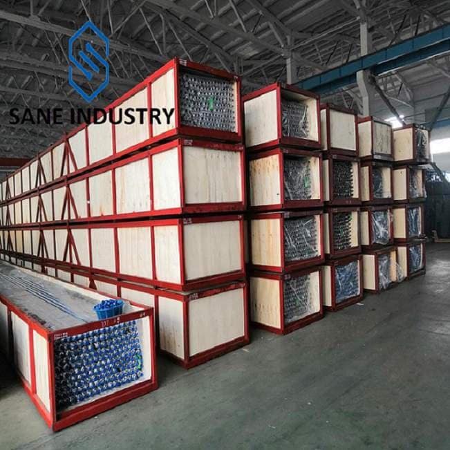
Our Production Capacity of L Finned Tubes, LL Fin Tubes, KL Fin Tubes
Total six L, LL, KL-Foot fin tube machines, monthly production capacity is 180,000 meters in total.
Comparison with Other Finned Tubes
| Parameter | L Type Fin Tube | Spiral Fin Tube | Longitudinal Fin Tube | Serrated Fin Tube |
|---|---|---|---|---|
| Fin Geometry | L-shaped, 90° vertical-horizontal bend | Helical, continuous spiral wrap | Straight, parallel to tube axis | Serrated edges, discontinuous |
| Heat Transfer Efficiency | High (↑25–35% vs. smooth tubes) | Moderate (↑15–25%) | Low (↑5–15%) | Very High (↑30–45%) |
| Pressure Drop | High (↑15–40%) | Moderate (↑10–20%) | Low (↑5–10%) | Very High (↑30–50%) |
| Manufacturing Cost | High (complex forming/welding) | Low (automated spiral wrapping) | Very Low (simple attachment) | Moderate (precision cutting) |
| Corrosion Resistance | Moderate (joint vulnerabilities) | High (seamless spiral bonding) | Low (edge gaps trap contaminants) | Low (serrations trap moisture) |
| Fouling Resistance | Low (turbulence traps particulates) | Moderate | High (smooth flow paths) | Very Low (serrations trap debris) |
| Space Efficiency | Compact (dense fin arrangement) | Bulky (wide spiral pitch) | Moderate | Compact |
| Thermal Stress Resistance | Moderate (cracking risk at joints) | High (uniform expansion) | Low (linear expansion mismatch) | Low (stress concentration) |
| Best Applications | Petrochemical, high-pressure boilers | HVAC, low-corrosion environments | Low-temperature exchangers | High-dust, aggressive cooling |
Why Choose Us
- a 16-year LL fin tubes supplier. We are experts.
- solutions for all your needs
- the highest product quality
- the low lead times
- excellent customer service