
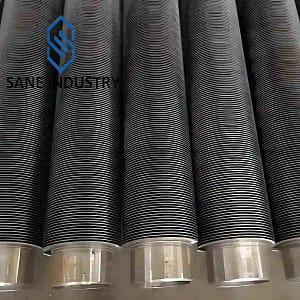
G Type Embedded Finned Tubes
Balanced Performance for Medium-Temperature Heat Exchangers
Tired of L-wrap fins that loosen after two years of thermal cycling? Hesitant to pay the premium for high frequency welded tubes when your operating temperature stays under 400°C?
G type embedded finned tubes solve this exact middle-ground problem. Also known as grooved finned tubes, they lock aluminum fins into machined spiral grooves on the base tube and roll the groove edges closed — creating a mechanical interlock far stronger than simple wrapped fins, at roughly half the cost of fully welded designs.
At SANE Industry, we manufacture embedded type fin tubes with tight tolerance groove machining and controlled rolling force, ensuring consistent fin retention even after thousands of thermal cycles. For air coolers, unit heaters and waste heat recovery systems running at 250–400°C, it’s the most cost-effective reliable solution on the market.
ISO 9001:2015 Certified
All manufacturing and testing in our factory are strictly in accordance with ISO standards.
Rich Industry Experience
Specializing in the production of finned tubes for over 15 years, serving more than 100 clients worldwide.
The Strictest Quality Control
From raw materials to the final product, every stage is strictly controlled for quality. TÜV, SGS, BV inspection available.
Full Material Traceability
We ensure full traceability via EN 10204 3.1 or 3.2 mill test certificates and complete records throughout the entire process.
What Are G Type Embedded Finned Tubes?
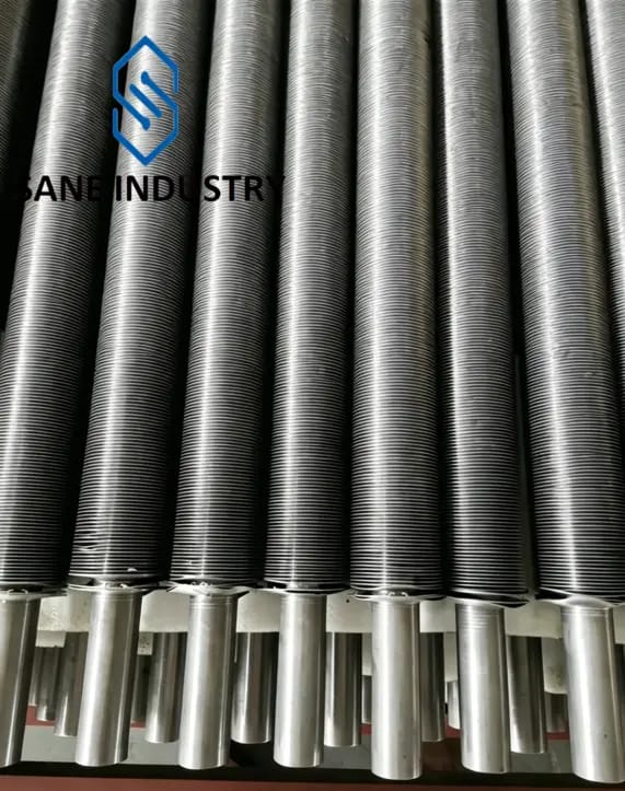
An embedded fin tube — also called a G finned tube, grooved fin tube, or G type embedded finned tube — is a finned tube where the fin is mechanically locked into a spiral groove precision machined into the outer surface of the base tube. A continuous aluminum or copper fin strip is fed into the groove under tension, and the tube material on both sides of the groove is rolled back over the fin foot, permanently trapping it in place.
This is fundamentally different from a welded or wrapped construction. The fin is not fused to the tube by a weld. It is not held by tension alone. It is physically embedded — mechanically interlocked into a channel that prevents radial and axial movement. The result is a finned tube that withstands vibration, thermal shock, and high-temperature flue gas without fin loosening.
The “G” in G-fin comes from the cross-sectional shape of the fin foot after embedding — it resembles the letter G, with the fin strip folded at the base and locked under the rolled tube material. The grooved fin tube name describes the same product from the manufacturing side: a groove is precision machined, and the fin is embedded into it.
At SANE Industry, we produce embedded finned tubes with aluminum or copper fins on carbon steel or stainless steel base tubes. Every tube ships with bare, unfinned ends as standard — ready for rolling or welding into your tube sheet.
Mechanical Interlock
Fin foot trapped in a spiral groove, rolled tight on both sides.
Bare Ends Standard
Unfinned tube ends on every piece, no extra charge.
Thermal Shock Resistant
The embedded bond handles rapid temperature swings without relaxing.
Anatomy of a SANE G Type Embedded Fin Tubes
An embedded type fin tube from SANE Industry consists of four functional elements:
Base Tube: A seamless carbon steel, stainless steel or copper tube — the pressure boundary and structural core. We use ASTM A179, A192, A210, A106B for carbon steel, C44300, C71500 for copper, and 304/304L or 316/316L for stainless.
Spiral Groove: A continuous helical channel machined into the outer surface of the base tube. Groove depth, width, and pitch are precisely controlled to match the fin strip dimensions.
Fin Strip: Continuous aluminum strip — typically 1050 or 1060 grade — fed into the groove under controlled tension. The strip forms a vertical fin along the tube.
- Rolled Shoulder: After the fin strip is seated in the groove, the tube material on both sides of the groove is mechanically rolled back over the fin foot. This traps the fin in place, creating the characteristic G-shaped cross-section that gives the G fin tube its name.
The mechanical interlock is the defining structural feature. Unlike a wrapped fin, which relies on residual tension that can relax, the embedded fin is physically trapped. Unlike a welded fin, there is no heat-affected zone and no risk of weld cracking under thermal cycling.

Core Advantages — Why Engineers Specify G Type Embedded Fin Tubes
1. 3–4x Stronger Retention Than L-Wrap Fins
The mechanical interlock of the grooved fin tube design means fins will not unwind, lift or separate under normal operating conditions. In our in-house thermal cycling testing, G-type fins retained 92% of their original contact pressure after 5,000 cycles, compared to just 28% for L-wrap fins.
2. Significantly Lower Cost Than Fully Welded Tubes
G type embedded finned tubes deliver approximately 80% of the performance of high frequency welded tubes at roughly 50–60% of the cost. For medium-temperature applications below 400°C, this makes them the most cost-effective reliable option on a total cost of ownership basis.
3. Stable Performance Up to 400°C
Unlike wrapped fins that lose tension rapidly above 250°C, properly manufactured embedded fin tubes maintain consistent thermal contact up to 400°C continuous operating temperature. This covers the vast majority of industrial air cooler and unit heater applications.
4. Excellent Vibration Resistance
The crimped groove lock holds fins firmly in place even under high vibration conditions such as compressor coolers and marine engine cooling systems. Fins will not rattle loose or shift position over time.
5. Wide Material Compatibility
We can produce aluminum embedded finned tube on carbon steel, stainless steel or copper base tubes, matching the base material to your process fluid and corrosion requirements while using aluminum fins for optimal air-side heat transfer.
6. Clean, Uniform Appearance
The embedded fin root creates a neat, professional finish with no exposed weld spatter or sharp edges. Tubes are easier to handle during heat exchanger assembly and less prone to shipping damage.
How SANE Industry Manufactures G Type Embedded Finned Tubes
The core manufacturing process of a G type embedded aluminum fin tube follows a three-stage sequence: groove, embed, lock.
Stage 1 — Grooving
A continuous spiral groove is cut into the outer surface of the seamless base tube. The groove depth, width, and pitch are CNC-controlled and matched to the fin strip dimensions. The groove geometry is critical — too shallow, and the fin won’t lock. Too wide, and the rolled shoulder won’t close over the fin foot. Our grooving parameters are qualified by procedure for each tube diameter and fin specification.
Stage 2 — Fin Embedding
Aluminum fin strip — typically 1050 or 1060 grade, 0.3mm to 0.5mm thick — is fed into the spiral groove under controlled tension. The strip is folded at the base to form the characteristic G-shaped foot. As the tube rotates, the fin feeds continuously into the groove, forming a uniform helical fin along the tube.
Stage 3 — Rolling and Locking
Immediately after the fin strip is seated, rolling tools press the tube material on both sides of the groove back over the fin foot. This traps the fin mechanically. The rolled shoulder provides positive retention — the fin cannot move radially outward, and it cannot slide along the groove. The resulting grooved fin tube is inspected for fin tightness, pitch consistency, and shoulder closure.
We have total six G type embedded fin tubes production lines, monthly production capacity is 180,000 meters in total.

G Type Embedded Fin Tube Technical Specifications
| Parameter | Our Standard Capability |
|---|---|
Base Tube OD |
19 to 73 mm |
Base Tube Wall Thickness |
1.5 to 8 mm |
Base Tube Length |
≤32,000 mm |
Base Tube Material |
Carbon steel (ASTM A179, A192, A106 Gr. B, etc.) , stainless steel (304/316L, etc.), alloy steel, copper (C12200), Cu-Ni (C70600), titanium |
Fin Pitch |
2.1 to 10 mm |
Fin Height |
5 to 20 mm |
Fin Thickness |
0.4 to 1 mm |
Fin Material |
aluminium (1060, 6063, etc.), copper |
End Finishes |
Plain ends, beveled ends |
Material Options for G Type Embedded Fin Tube
When designing a G type embedded finned tube — also commonly called a grooved fin tube — the base tube must have enough wall thickness so that the remaining metal under the groove still handles the design pressure, and it needs a certain amount of ductility for the rolling operation to lock the fin tight. Below are the standard material choices.
Base Tube Materials:
- Carbon steel (SA 179, SA 192, A106B): For medium-to-low pressure steam, hot water, and thermal oil. External corrosion protection is typically required.
- Low-alloy heat-resistant steel (15CrMo, 12Cr1MoV, T11, T22): For high-temperature, high-pressure superheated steam or flue gas exposure.
- Stainless steel (304, 304L, 316, 316L, 2205): Used when the tube-side medium is corrosive or a sanitary external surface is specified.
- Copper-nickel (CuNi 90/10, 70/30): For seawater or brackish water cooling duty.
Fin Strip Materials:
- Aluminum (1050, 1060, 1100, 3003): Lightweight, thermally responsive, and naturally weather-resistant. Service temperature ≤200°C. This is by far the most common fin material on G type embedded fin tubes used in air coolers and HVAC systems.
- Copper: Exceptional thermal conductivity and corrosion resistance. Ideal for refrigeration and clean environments, though its density and cost are higher.
Quick-Reference Table of Common Material Pairings
| Service Condition | Base Tube Material | Fin Material | Typical Application |
|---|---|---|---|
Low-to-medium temperature clean air cooling, low-pressure steam inside |
Carbon steel |
Aluminum |
HVAC heating coils, unit heaters |
Seawater or brackish water cooling, air on the outside |
CuNi 90/10 or titanium |
Aluminum or copper |
Coastal power plants, marine coolers |
Refrigeration evaporator/condenser |
Copper |
Copper or aluminum |
Industrial chillers |
Mildly corrosive process fluids and food-grade applications |
304/316L |
Aluminum |
Food & beverage processing |

Where G Type Embedded Finned Tubes Are Installed
G type embedded finned tubes, also widely referenced as grooved finned tubes in engineering specifications, deliver stable, dependable heat transfer performance across heavy industrial operations. Below are their primary use cases and standard configuration pairings:
Petrochemical Processing
Applied equipment: Refinery air coolers, gas coolers, overhead condensers, hydraulic oil coolers
Standard configuration: Carbon steel or stainless steel base tubes with aluminum fins; anti-corrosion coatings are available for sulfur-bearing operating environments
Core value: Unlike welded fin designs, the grooved fin tube structure eliminates weld-related crevice corrosion risks, preserving consistent heat transfer efficiency with minimal performance degradation over extended service life.
Power Generation
Applied equipment: Power plant air coolers, boiler economizers, flue gas waste heat recovery units, turbine cooling systems
Standard configuration: Carbon steel SA106 Gr.B base tubes with aluminum fins
Core value: These g type embedded fin tubes withstand continuous flue gas temperatures of 300–400°C and hold up reliably under frequent start-stop thermal cycles, while carrying a lower upfront cost compared to fully extruded fin solutions.
Metallurgy & Building Materials
Applied equipment: Blast furnace waste heat recovery systems, reheating furnace flue gas cooling, profile quenching cooling systems
Standard configuration: Carbon steel base tubes with steel or aluminum fins
Core value: Built to resist dust abrasion and high-temperature oxidation, g type embedded finned tubes maintain tight, secure fin attachment even under repeated thermal expansion and contraction, avoiding the fin loosening issues common with basic tension-wound fin tubes.
Natural Gas & Oilfield Operations
Applied equipment: Natural gas line heaters, wellhead cooling units, compressor interstage coolers
Standard configuration: Carbon steel or alloy steel base tubes with aluminum fins
Core value: Backed by their robust mechanical interlock construction, grooved finned tubes deliver strong pressure-bearing capacity and high operational reliability for remote field and outdoor unmanned installations.
Marine & Offshore Engineering
Applied equipment: Marine diesel engine cooling systems, seawater desalination preheaters, offshore platform air cooling units
Standard configuration: Copper-nickel alloy base tubes with copper or aluminum fins
Core value: The base tube alloy provides proven resistance to seawater corrosion, while the embedded grooved design prevents crevice corrosion at the fin-to-tube interface — a critical performance benefit for coastal and offshore service environments.
Food & Beverage Processing
Applied equipment: Pasteurization cooling units, process water chillers, syrup cooling systems, CIP system heat exchangers, beverage dispensing cooling coils
Standard configuration: 304/316L stainless steel base tubes with pure aluminum or copper fins
Core value: For sanitary production environments, g type embedded finned tubes eliminate weld seams and crevices that trap residue and bacteria, making cleaning and sanitization far simpler. The cold-formed grooved fin tube design introduces no thermal distortion or contamination, preserving full food-grade compatibility for dairy, beverage and food processing lines.
Quality Assurance — How We Verify Every Grooved Finned Tube
With grooved finned tubes, most performance problems trace back to one of three root causes: a groove that’s too shallow to hold the fin, a fin strip that wasn’t seated fully to the bottom of the groove, or rolling force that’s inconsistent along the tube length. These flaws don’t show up on a quick visual check — they reveal themselves after 2–3 years in service as fins lift off and heat transfer drops.
At SANE Industry, we don’t rely on a final eyeball inspection. Every g type embedded finned tube must clear six mandatory quality gates from raw material to finished product, with measurable pass/fail criteria at every step.
Gate 1: Base Tube Verification & Groove Machining Validation
Before any fin material touches the tube, we inspect every incoming lot of base tube against its mill certificate — chemistry, OD, wall thickness and surface condition — to the applicable ASTM or EN standard. We then validate the grooving tool setup on a test piece, measuring groove depth, width and profile to within 0.02mm. A groove that’s even 0.1mm too shallow will not hold the fin under thermal cycling; we catch that before production starts.
Gate 2: Fin Strip Material & Dimensional Check
Aluminum fin strip for aluminum embedded finned tube production is verified for alloy chemistry, hardness uniformity and edge condition. Strip thickness and width are checked across every coil. Uneven hardness causes inconsistent seating in the groove; burrs on the strip edge prevent full contact at the groove bottom. Any coil that fails is returned to the mill — we never run off-spec material to save cost.
Gate 3: In-Process Seating & Rolling Force Monitoring
Our embedding machines run with closed-loop rolling force control. As the tube rotates and advances, the seating roller and closing roller forces are sampled continuously and logged against the qualified manufacturing procedure specification. If force drifts outside the approved window, the line auto-stops. On top of automation, our QC inspector pulls one tube out of every ten for visual check. The fin root shall be fully seated at the bottom of the groove, free of curled edges, root gaps and misalignment.
Gate 4: Destructive Pull-Out Test Per Batch
From every production batch, we cut test samples and perform a full fin pull-out test to measure the actual force required to extract the fin foot from the groove. A valid embedded joint fails by shearing the aluminum fin foot, not by pulling cleanly out of the groove. If any sample fails the pull-out force requirement, the entire batch is quarantined and reworked or scrapped.
Gate 5: Final Dimensional & Visual Release Inspection
Every tube receives a 100% final check against the approved drawing: fin height, fin pitch, overall length, tube straightness and finned length. We also run a full visual check for missing fins, crushed fins, groove closure defects and surface damage. Any tube that fails is set aside, root-caused, and the process is corrected before production continues.
Gate 6: Pressure Test & Full Traceability Documentation
100% of G finned tubes undergo hydrostatic pressure testing at 1.5 times the rated working pressure, with zero leakage as the only pass criterion. Every tube is marked with a unique identification number that links back to base tube MTRs, aluminum coil heat numbers, inspection records and pressure test results. We supply EN 10204 3.1 certificates as standard, with EN 10204 3.2 third-party witnessed inspection available for capital projects.
Extruded vs. Welded vs. Wrapped vs. Embedded G Fin Tubes — How to Choose
| Feature | Extruded Fin Tube | High Frequency Welded Fin Tube | Wrapped Fin Tube (L/LL/KL) | Embedded Fin Tube (G-Fin) |
|---|---|---|---|---|
Fin-to-Tube Interface |
None — integral |
Metallurgical weld |
Mechanical tension |
Mechanical groove |
Fin Material Options |
Aluminum primarily |
Carbon steel, alloy steel, stainless steel |
Aluminum primarily |
Aluminum primarily |
Contact Resistance |
Zero |
Zero |
High (air gap under fin foot) |
Moderate (micro-gap remains at groove interface) |
Max Continuous Operating Temp |
300°C (572°F) |
Up to 650°C (1200°F) |
Up to 250°C (482°F) |
Up to 400°C (752°F) |
Corrosion & Fouling Resistance |
Excellent |
Fair |
Very poor |
Poor |
Vibration & Thermal Cycling Resistance |
Excellent |
Excellent |
Poor |
Fair |
Typical Service Life (Industrial) |
20–30 years |
15–25 years |
3–5 years |
5–8 years |
Upfront Cost |
Medium |
Medium |
Low |
Medium–High |
10-Year Total Cost of Ownership |
Lowest |
Low |
Very high |
High |
Best For |
Corrosive/coastal environments, air coolers, long-service HVAC projects |
High-temperature boilers, high-pressure waste heat systems |
Low-temperature indoor HVAC, budget temporary projects |
Medium-temperature dry industrial air coolers |
A Quick Selection Guide:
Choose G Type Embedded Finned Tubes When:
- Operating temperatures between 250°C and 400°C — a range that exceeds the temperature limit of extruded aluminum fin tubes, yet does not demand the extreme heat resistance of high frequency welded steel fin tubes. G type embedded finned tubes deliver reliable, stable performance in this medium-high heat window as a balanced, cost-effective solution.
- Facilities with frequent start-stop cycles and repeated thermal expansion and contraction, where fin loosening is a top concern. The mechanical interlock design of grooved finned tubes locks fins firmly in place, far outperforming basic tension-wound fins under cyclic thermal stress.
- Projects with constrained budgets that cannot justify the premium cost of extruded aluminum fin tubes, but cannot accept the short service life and high maintenance of standard wound fin tubes. G type embedded fin tubes strike an optimal balance between upfront cost and long-term durability.
- Equipment subject to continuous vibration, such as internal combustion engines, generator sets and construction machinery. The robust mechanical lock of g type embedded finned tubes prevents fin shifting or detachment, maintaining consistent heat transfer performance even under constant mechanical stress.
- Applications requiring high base tube pressure ratings, where welding-induced heat damage to the base tube’s mechanical properties is unacceptable. As an all-cold-formed grooved fin tube solution, this process introduces no weld heat-affected zone, preserving the full pressure-bearing integrity of the base material.
G Type Embedded Finned Tubes Are Not Recommended When:
- Highly corrosive coastal or chemical atmospheric environments. Extruded aluminum fin tubes feature a fully encapsulated base tube structure for superior corrosion protection, while the exposed base tube at the groove edges of g type embedded fin tubes carries a higher risk of crevice corrosion in aggressive atmospheres.
- Applications demanding maximum heat transfer efficiency. For the same tube dimensions, extruded fin tubes achieve a higher fin ratio and near-zero thermal contact resistance, delivering over 15% better overall heat transfer performance than grooved finned alternatives.
- Ultra-high temperature (>450°C) flue gas applications with strong corrosive content. High-frequency welded steel fin tubes are the proper choice here, as aluminum fins will oxidize and degrade rapidly at these extreme temperatures.
- Ambient-temperature projects with extremely tight budget constraints. L-type tension-wound fin tubes come at a much lower cost and are fully adequate for light-duty, low-temperature operating conditions.

Customer Success Story — Grooved Fin Tube Proven in Service
2.5x Longer Service Life for Industrial Unit Heaters
Customer: Large facility management company operating 12 manufacturing plants across the US Midwest
Challenge: Their existing L-wrap fin tube unit heaters were failing every 3–4 years as fins loosened and heat output dropped. Full welded tube replacements were outside their maintenance budget.
SANE Solution: We recommended our standard g type embedded finned tube replacement bundles as a drop-in upgrade. The mechanical groove lock eliminated the fin loosening problem, at roughly 55% of the cost of fully welded tubes.
Result: The upgraded heaters have now been in service for 9 years with no measurable drop in heat output. The customer has extended their heater replacement cycle from 4 years to 10+ years, reducing annual maintenance spend by over 60%.
65% Less Maintenance for Gas Compressor Coolers
Customer: Midstream natural gas operator with 8 compressor stations in the Texas Panhandle, US
Challenge: Reciprocating compressor vibration and 320°C discharge temperatures loosened L-wrap fins in 2–3 years, causing 30% heat loss and frequent summer shutdowns. Cheap imported G type fin tubes failed just as fast due to shallow grooves and poor rolling; fully welded tubes were twice the budget.
SANE Solution: Drop-in replacement bundles of our standard g type embedded finned tube — carbon steel base, aluminum fins, precision 0.4mm grooves and controlled roll closure for vibration-resistant retention. We supplied full documentation and matched existing dimensions to avoid shell modifications.
Result: 7 years in continuous service with <5% thermal degradation. Tube replacement cycle extended from 3 to 8+ years, cutting annual cooler maintenance spend by 65%. Five more stations have since been retrofitted with our grooved finned tube bundles, eliminating seasonal high-temperature shutdowns entirely.
Frequently Asked Questions
Q: What is the difference between G type embedded finned tube and regular L-wrap fin tube?
A: The core difference is fin retention. L-wrap fins are simply folded and tension-wrapped around the tube, held only by friction; they loosen rapidly as temperatures rise above 250°C. A g type embedded finned tube seats the fin foot into a machined spiral groove and rolls the groove edges closed, creating a mechanical interlock that holds 3–4 times longer under thermal cycling. For any application running above 200°C, G-type will almost always deliver lower total cost of ownership.
Q: How do G type fin tubes compare to extruded fin tubes in performance?
A: Extruded fin tubes have a seamless aluminum sleeve that fully encapsulates the base tube, giving them superior corrosion resistance and slightly lower thermal contact resistance. G finned tubes have a higher temperature rating (400°C vs 300°C) and a lower upfront cost. For dry, medium-temperature indoor applications, g fin tube is usually the better economic choice; for humid, coastal or outdoor service, extruded fin tubes will last much longer.
Q: What is the maximum operating temperature for G finned tubes?
A: For standard carbon steel base tube with aluminum fins, we rate g finned tubes for continuous service up to 400°C (752°F). Above this temperature, differential thermal expansion between the aluminum fin and steel base tube causes the fin to lose contact pressure in the groove, and thermal performance degrades over time. For higher temperatures, we recommend our high frequency welded fin tube range.
Q: What does the "G" in g type embedded fin tubes mean?
A: The “G” describes the cross-sectional shape of the fin foot after embedding. When the aluminum strip is folded at the base and locked under the rolled tube material, the profile resembles the letter G. A G fin tube and a grooved fin tube are the same product described from different perspectives — the fin shape versus the manufacturing method.
Q: Do G type embedded fin tubes suffer from crevice corrosion in the groove?
A: No. The fin root is locked inside the machined groove of the base tube by cold back-rolling, creating a positive mechanical lock. This structure resists thermal expansion and contraction far better than simple tension-wound fins, maintaining stable thermal performance throughout the service life.
Q: Will the fins loosen after long-term thermal cycling?
A: In dry indoor environments, crevice corrosion is generally not a concern. In humid, coastal or chemically aggressive outdoor environments, moisture and contaminants can become trapped in the groove interface and accelerate corrosion. For these environments, we typically recommend extruded bimetallic fin tubes with full aluminum encapsulation instead. We will always be upfront about this limitation during quotation.
Q: Can you manufacture G fin tubes to match our existing heat exchanger drawings?
A: Yes, this is our standard workflow. Send us your drawing or sample tube with fin height, fin pitch, base tube size and length, and we will produce grooved finned tubes as exact drop-in replacements. We can also reverse-engineer tubes from failed samples if drawings are not available. Our engineering team will also flag any design improvements that would extend service life.
Q: What is your minimum order quantity for G type embedded finned tubes?
A: For standard catalog sizes, our MOQ starts at 100kg for small trial and replacement orders. For custom sizes and non-standard materials, MOQ typically ranges from 300–500kg depending on complexity. We regularly supply small replacement batches for plant shutdowns and maintenance projects.
Q: What base tube and fin materials are available for grooved fin tubes?
A: The most common configuration is carbon steel (A179, A106 Gr.B) base tube with 1060/3003 aluminum fins — this is our standard aluminum embedded finned tube. We also produce grooved fin tubes with 304/316L stainless steel base tubes for corrosive process fluids, and copper base tubes for high-efficiency refrigeration applications. Custom material combinations are available on request.
Q: What is your typical lead time, and do you ship worldwide?
A: Standard sizes in stock: 5–7 working days. Custom production runs: 30–40 working days. Expedited production is available for emergency shutdown projects.
As a global g fin tube manufacturer, we ship regularly to over 30 countries across North America, Europe, the Middle East, Southeast Asia and Oceania. We handle all export documentation and can arrange sea, air or door-to-door delivery.
Specify Your G Type Embedded Fin Tubes — Get a Quote Within 24 Hours
Direct Contact
- allen@sanesteel.com
- +8617766383215
- +8617766383215
If you’ve been replacing wrapped fins every few years and don’t need the full temperature rating of welded tubes, G type embedded finned tubes are almost certainly your lowest total cost of ownership solution.
At SANE Industry, we don’t push one technology over another. We’ll analyze your operating conditions, walk you through the tradeoffs, and recommend the fin type that makes the most engineering and economic sense for your project — even if it’s not the most expensive one.
Other Finned Tube Products You May Need
Additional Resources for Engineers and Procurement Teams
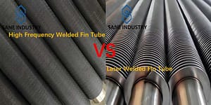
High Frequency Welded Fin Tubes vs Laser Welded Fin Tubes
High Frequency welded fin tubes and laser welded fin tubes are two dominant technologies in industrial heat exchange systems, each engineered for distinct operational demands.
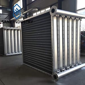
What is a Finned Tube Heat Exchanger?
Finned tube heat exchangers are specialized thermal transfer devices designed to enhance heat exchange between two fluids with significantly different heat transfer coefficients. These exchangers
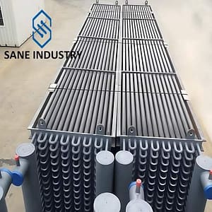
How Does a Fin Tube Radiator Work 2025?
Fin tube radiators, as indispensable heat exchange equipment in modern industrial and civilian fields, play a crucial role in multiple industries including energy, chemical engineering,

What is a fin tube? A complete guide 2025
Fin tubes(Finned tubes), as indispensable high-efficiency heat exchange components in modern industry, significantly enhance heat transfer efficiency by increasing the heat transfer surface area, playing

What is the difference between a bare tube and a finned tube?
Bare tubes and finned tubes represent two fundamental categories of heat transfer components used across various industrial applications. While both serve the purpose of facilitating

What is a finned tube? The use and advantage of a finned tube?
A finned tube is a heat-transfer tube enhanced with metal fins to boost surface area and improve thermal efficiency. It’s widely used in heat exchangers,

What are the differences between seamless and welded Pipe?
Steel pipes are fundamental components in various industries, including oil and gas, construction, automotive, and manufacturing. The two primary types of steel pipes – seamless

How many types of finned tubes are there?
Finned tubes are essential components in heat exchangers, designed to enhance heat transfer efficiency by increasing the surface area available for thermal exchange. These tubes