What is an Integral High Finned Pipe
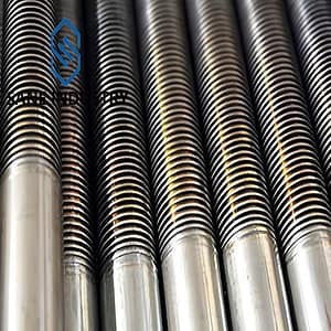
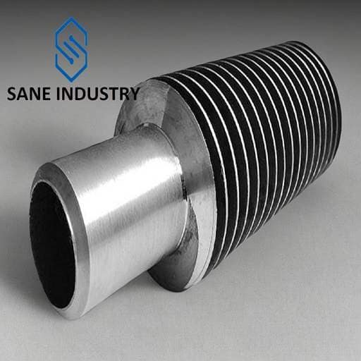
An integral high finned pipe is a specialized heat transfer component featuring high fins (typically 3mm or greater) that are integrally formed with the base tube, creating a single-piece structure that enhances heat transfer efficiency. This design differs from conventional finned pipe where fins are mechanically attached or welded separately. The integral structure provides superior mechanical strength and thermal performance, making it ideal for demanding industrial applications.
Key Structural Features of an Integral High Finned Pipe
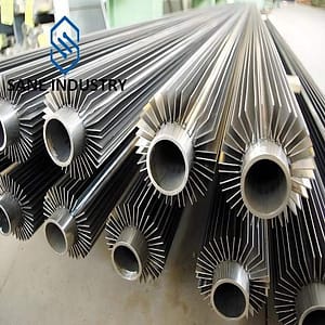
- Base Tube: The core tube, usually made of materials like copper, aluminum, stainless steel, or carbon steel, through which the primary fluid (liquid or high-velocity gas) flows.
- Extended Fins:
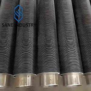
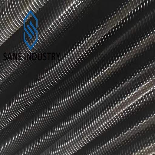
- Fins are 10–15 mm in height (far taller than low-fin tubes) and may be arranged in helical or longitudinal patterns.
- Fin density ranges from 50 to 125 fins per meter, depending on the application.
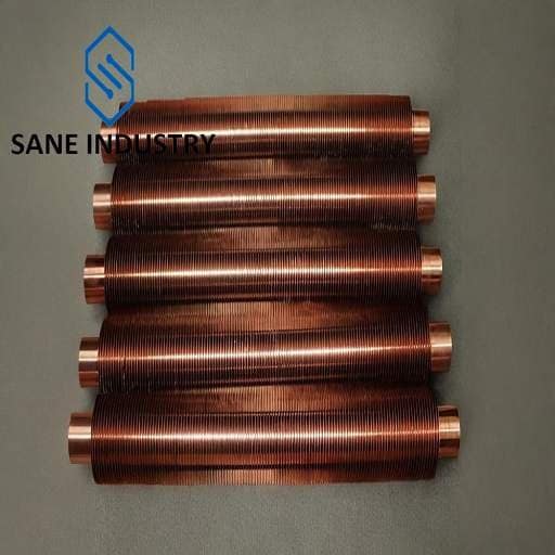
- Materials often include aluminum (for corrosion resistance) or copper (for high thermal conductivity).
The Manufacturing Process of Integral High Finned Pipes
Material Selection and Properties
- Aluminum Alloys: Lightweight and excellent thermal conductors, aluminum alloys are widely used in air-cooled heat exchangers and refrigeration applications. Their relatively soft nature makes them easier to form into high fins.
- Copper Alloys: Offering superior thermal conductivity, copper and copper-nickel alloys are preferred for high-performance applications where heat transfer efficiency is paramount. These materials are more challenging to form but provide excellent durability.
- Stainless Steels: For high-temperature or corrosive environments, stainless steel versions are available, though these typically have lower fin heights due to the material’s hardness.
Advanced Manufacturing Techniques
- Rotary Rolling Process: This technique involves passing the tube through rotating rollers that simultaneously form the fins and elongate the pipe axially. The process requires precise control of roller geometry and feed rates to achieve the desired fin characteristics.
- Planing and Extruding Methods: Use plaining tools that cut and extrude material to form high fins. The “plowing-extruding based on variational feed” method allows for the production of particularly tall fins by utilizing overlapping tool paths.
- Hot Extrusion: For certain materials and designs, hot extrusion processes are employed where the tube and fins are formed in a single operation under high temperature and pressure.
The Advantages of Integral High Finned Pipes
Enhanced Heat Transfer Density
Tall fins increase surface area by 5–10x vs. smooth tubes, maximizing thermal efficiency in high-temperature applications (e.g., boilers, thermal oxidizers).Monolithic Durability
Fins and tube form a single-material structure, eliminating weak joints or bonding interfaces prone to failure under thermal cycling or vibration.Corrosion Resistance
Seamless design avoids crevices; compatible with corrosion-resistant alloys (stainless steel, nickel-based) for acidic or high-moisture environments.High-Pressure Tolerance
Cold-worked fins retain base tube strength, handling pressures >50 bar without deformation, ideal for power plants or petrochemical systems.Low Maintenance
No fouling-prone gaps between fins and tube, reducing downtime in gas or clean-fluid applications.Material Versatility
Compatible with ductile metals (copper, aluminum, carbon steel) for tailored thermal/mechanical performance.
The Disadvantages of Integral High Finned Pipes
Fouling Susceptibility
Tight fin spacing traps particulates or viscous fluids, increasing maintenance in dusty or high-fouling environments (e.g., wastewater, sludge).Limited Material Options
Requires ductile metals (e.g., copper, aluminum) for cold-forming fins; incompatible with brittle alloys or ceramics for extreme corrosion/heat scenarios.High Initial Cost
Precision cold-working processes (rolling/extrusion) demand specialized equipment, raising production costs vs. welded or bonded alternatives.Reduced Flow Efficiency
Dense fins create turbulence in high-velocity fluids, risking pressure drop and energy losses in pumped systems.Mechanical Vulnerability
Tall fins (6+ mm) are prone to bending or damage during handling, limiting use in high-vibration or abrasive settings.Design Inflexibility
Fixed fin geometry (height, pitch) during manufacturing restricts post-production customization for niche applications.
Sizes and Materials of Our Integral High Finned Pipes
| Base Tube Diameter | 32 to 51 mm | 1. 1/4″ to 2″ NPS |
| Base Tube Wall Thickness | 4 to 8 mm | 0.16″ to 0.31″ |
| Base Tube Length | ≤32,000 mm | ≤92 ft |
| Base Tube Material | Carbon Steel (A106B, P235GH, A179, A210, A192, etc.) Alloy Steel (P5, T5, P9, T9, T11, T22, etc.) Stainless Steel (TP304, TP316, TP347, B407 800H/HT, etc.) aluminum, copper, titanium | |
| Fin Pitch | 50 to 125 FPM | 2 to 5 FPI |
| Fin Height | 3 to 15 mm | 0.118″ to 0.59″ |
| Fin Thickness | 1.6 to 2 mm | 0.063″ to 0.079″ |
| Fin Material | Same as base tube | |
| Fin Type | Integral high | |
For other customized requirements for Integral High Finned Pipes, please contact us.
What is the Price of Integral High Finned Pipes
Please contact our sales manager Allen@sanesteel.com.
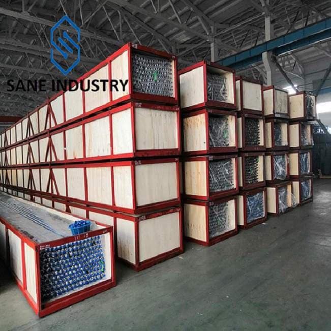
Our Production Capacity of Integral High Finned Pipes
Total three integral high finned pipe machines, monthly production capacity is 450,000 tons in total.
Application of Integral High Finned Pipes
- Power Plants:
- Surface finned pipe condensers: For efficient steam-to-water conversion
- Finned pipe economizers: Waste heat recovery with 15-20% efficiency improvement
- Finned pipe air preheaters: Enhancing boiler system performance
- Chemical Processing:
- Finned pipe reactor cooling systems: Precise temperature control
- Finned pipe distillation columns: Improved separation efficiency
- Finned pipe cryogenic applications: Withstands extreme temperatures
- HVAC Systems:
- Finned pipe air-cooled condensers: Lightweight yet durable construction
- Finned pipe chillers: High thermal conductivity for efficient cooling
- Finned pipe radiators: Compact design with superior heat dissipation
- Heat Exchanger Applications:
- Finned pipe air coolers: In these applications, the finned side is exposed to air while the tube side carries the process fluid. The high fin density maximizes air-side heat transfer, making the units more compact.
- Finned pipe boilers and economizers: Used in both water-tube and fire-tube boilers, these pipes enhance heat transfer from combustion gases to water/steam, improving overall efficiency.
- Finned pipe refrigeration systems: In evaporators and condensers, the pipes help achieve high heat transfer rates with minimal refrigerant charge, improving system efficiency.
- Finned pipe process heat exchangers: Chemical and petrochemical plants use these pipes in various process heating and cooling applications where reliable, efficient heat transfer is critical.
Compared to Regular Finned Pipe
| Feature | Integral High Finned Pipe | Conventional Finned Pipe |
| Bond Strength | Metallurgical bond (>120 MPa) | Mechanical/welded bond (80-100 MPa) |
| Thermal Efficiency | 15-20% higher heat transfer | Standard performance |
| Pressure Rating | Up to 3.2 MPa | Typically <2.5 MPa |
| Temperature Range | -50°C to 250°C | Limited by attachment method |
| Lifespan | 2-3x longer | Subject to fin detachment |
Why Choose Us
- a 16-year high fin tube manufacturer. We are experts.
- solutions for all your finned tube needs
- the highest product quality
- the low lead times
- excellent customer service