What is an H Finned Tube
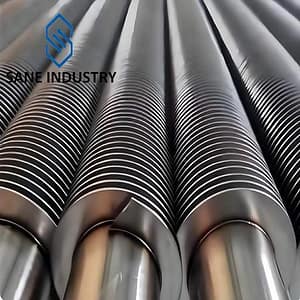
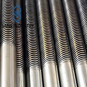
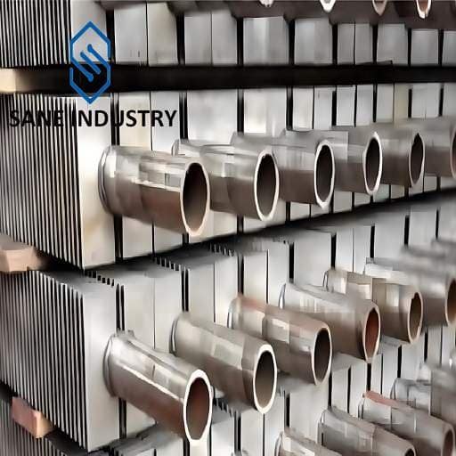
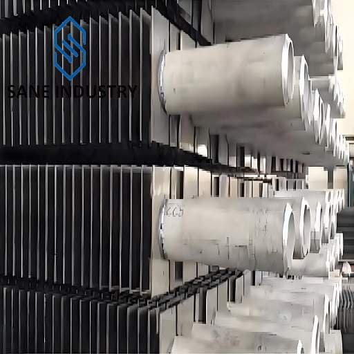
An H-fin tube (or H-type finned tube, also known as square finned tube or plate finned tube) is a specialized heat exchange component designed to enhance thermal efficiency in high-temperature or high-fouling environments. Its name derives from the distinctive “H” shape formed by symmetrically welded fins on the outer surface of a base tube.
Structure of H Finned Tubes
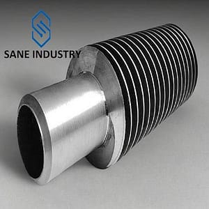
- Base Tube: Typically a seamless metal tube (carbon steel, stainless steel, or alloy) that channels fluids (e.g., water, steam, or gas).
- Fins: Two parallel steel strips are welded vertically along the tube’s length on opposite sides, creating an H-shaped profile. The fins are often laser- or resistance-welded for durability.
Types of H Finned Tubes
- Single H-Type Finned Tubes : Single-layer fin structure for standard heat exchange requirements.
- Double H-Type Finned Tubes: Dual-layer fins for expanded heating surfaces and higher thermal efficiency.
The Manufacturing Process of H Finned Tubes
Material Preparation
- Base Tube Selection: carbon steel tubes, alloy steel tubes or stainless steel tubes are selected as the core material.
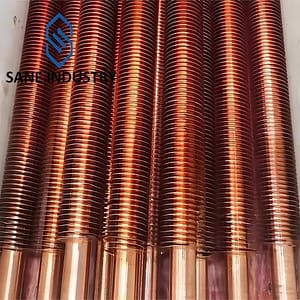
- Fin Strip Material: Aluminum, copper, or thin steel plates are selected for fins based on thermal conductivity and corrosion resistance. Materials are sheared to the required width.
Pre-Treatment
- Surface Cleaning: The base tube undergoes polishing or sandblasting to remove oxides, grease, and contaminants, ensuring strong adhesion with fins.
Fin Processing
- Stamping/Rolling: H-shaped fins are created using molds or continuous rolling. Fins feature a central ridge and vertical side extensions.
- Trimming and Shaping: Fin edges are calibrated to ensure uniformity and eliminate burrs/deformations.
Medium-frequency resistance welding
- Heats the fin root to fuse it seamlessly with the base tube.
The Advantages of H Finned Tubes
Enhanced Heat Transfer
The H-shaped fin design creates turbulence, disrupting thermal boundary layers and significantly boosting heat exchange efficiency by 25–40% compared to smooth tubes.Structural Stability
Welded joints resist thermal stress and vibration, ensuring long-term durability in high-pressure environments.Anti-Fouling Performance
Vertical fin gaps minimize ash/deposit buildup, reducing maintenance frequency in dusty or corrosive media.Corrosion Resistance
Customizable material pairings (e.g., stainless steel fins with alloy base tubes) extend service life in acidic/alkaline conditions.Space Efficiency
Compact fin density optimizes heat transfer surface area, ideal for constrained industrial layouts.Adaptability
Adjustable fin height (8–25 mm) and spacing (2–8 mm) cater to diverse thermal loads and flow regimes.
The Disadvantages of H Finned Tubes
Higher Manufacturing Costs
Complex machining and precision welding processes increase production expenses compared to simpler fin designs.Weight Limitations
Dense fin arrangements and thick base tubes may add excessive weight, restricting use in lightweight systems.Flow Resistance
Turbulence-enhancing fins create higher pressure drops, demanding stronger pumps or fans for fluid circulation.Limited Cleanability
Tight fin spacing traps particulates in high-fouling environments, requiring specialized cleaning tools.Corrosion Vulnerabilities
Exposed welded joints and fin edges risk accelerated degradation in highly acidic/alkaline media.Space Constraints
Bulkier dimensions compared to smooth tubes complicate retrofitting in compact systems.
Sizes and Materials of Our H Finned Tubes
| Base Tube Diameter | 25 to 73 mm | 1/2″ to 2 1/2″ NPS |
| Base Tube Wall Thickness | 2 to 12 mm | 0.08″ to 0.48″ |
| Base Tube Length | ≤32,000 mm | ≤92 ft |
| Base Tube Material | Carbon Steel (A106B, P235GH, A179, A210, A192, etc.) Alloy Steel (P5, T5, P9, T9, T11, T22, etc.) Stainless Steel (TP304, TP316, TP347, B407 800H/HT, etc.) | |
| Fin Pitch | 30 to 117 FPM | 1 to 3 FPI |
| Fin Height | 15 to 45 mm | 0.59″ to 1.78″ |
| Fin Thickness | 1.5 to 4 mm | 0.059″ to 0.16″ |
| Fin Material | Carbon Steel, 2.25Cr-1Mo, 5Cr-0.5Mo, 11-13Cr (409, 410), 18Cr-8Ni (SS 304), 25Cr-20Ni | |
| Fin Type | H, HH | |
For other customized requirements, please contact us.
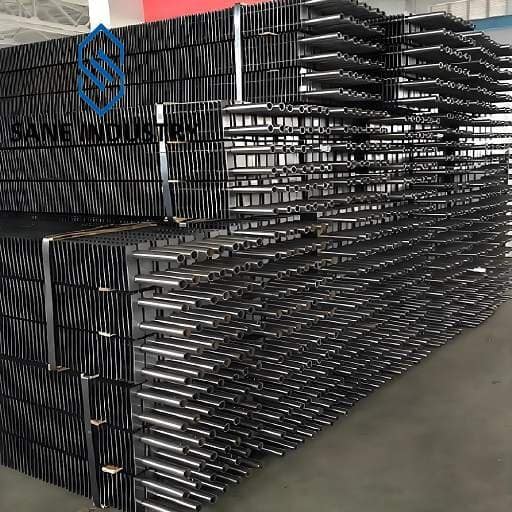
Our Production Capacity of H Finned Tubes
Total six medium frequency welded H-type fin tube machines, monthly production capacity is 1200 tons in total.
Application of H Finned Tubes
- Power Plants: Economizers, air preheaters, and waste heat recovery systems.
- Petrochemical: Gas coolers, process heaters, and condensers.
- HVAC: Industrial air handlers and heat recovery ventilators.
- Renewable Energy: Biomass boilers and geothermal systems.
Comparison to Other Types of Finned Tubes
| Type | H-Type | L-Type (Single Fin) | Helical |
|---|---|---|---|
| Fin Shape | Dual fins (H-cross section) | Single L-shaped fin | Spiral-wound fin |
| Efficiency | Highest (double surface area) | Moderate | High (but airflow drag) |
| Durability | Excellent (rigid structure) | Good | Moderate |
| Typical Use | High-velocity gas systems | General heat exchange | Liquid-to-gas heat transfer |
Why Choose Us
- A 16-year H fin tube manufacturer. We are experts.
- solutions for all your needs
- the highest product quality
- the low lead times
- excellent customer service